Extendiendo la red ethernet por la WAN
Fecha: junio del 2018
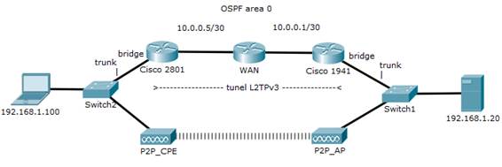
Escenario
Cuando se enseña CCNA1, siempre se hace hincapié en segmentar las redes LAN en
varios dominios de broadcast, diferentes subredes, etc.
A veces, en la vida real, por motivos X esto no es 100% posible y hay que extender el
segmento LAN tal como está, con sus broadcasts y mismo segmento IP a través de un
enlace de fibra o un punto a punto de radio.
El siguiente escenario, está basado en un caso real y presenta la misma problemática,
pero las distancias a cubrir necesitan de un enlace P2P por radio, y otro de backup vía
un proveedor de servicios WAN y utilizar un tunel de layer 2 para extender la LAN.
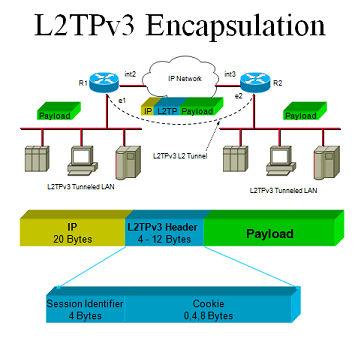
El protocolo utilizado aquí es L2TP, también se podría utilizar EoIP (Ethernet over IP).
En este caso, la trama ethernet, se transmite etiquetada en VLAN 100 por un port trunk,
y la recibe la interface Fa0/0 de un router Cisco 2801, sin subinterface en la VLAN 100 ni
nada por el estilo, la interface a diferencia de lo que estudiamos siempre, sin dirección IP
actúa como bridge reenviando a un pseudo-wire (cable virtual) formando un túnel desde
la interface Fa0/1 a una IP del extremo declarado en la configuración del tunel L2TP.
Utilizamos OSPF para resolver la conectividad, en la realidad se utilizaría MPLS y BGP.
En el otro extremo el proceso es el mismo, se desencapsula y reenvía en layer 2 al trunk de
un switch, y este reenvía la trama al dispositivo final.
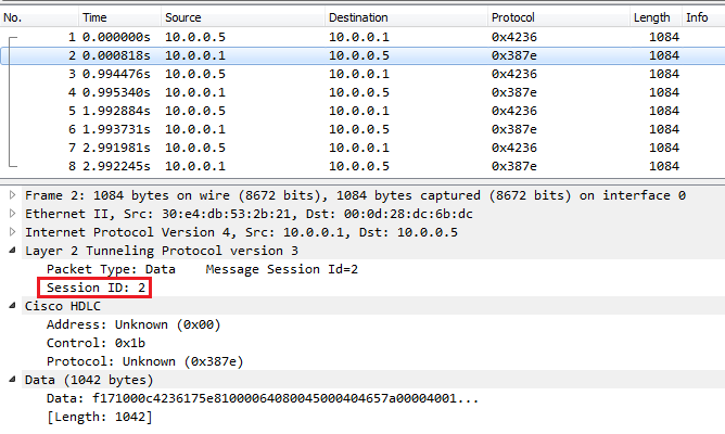
En este tunel, el payload (la trama original) no se puede decodificar con Wireshark, tal como
se observa en las capturas 2.2.1 y 2.2.2. El nivel de seguridad no se discute en este lab, pero
podría protegerse con IPSec sin problemas. Paradogicamente IPSec es de layer 3 y protegería
tráfico de layer 2 (pero recordemos que la trama aquí sólo es payload de un paquete IP).
1.- Configuración
necesaria:
1.1.- Router 1:
![]()
![]() pseudowire-class L2TP
pseudowire-class L2TP
encapsulation l2tpv3
protocol
none
ip local
interface GigabitEthernet0/1
!
interface GigabitEthernet0/0
description LAN
no ip address (para que trabaje como bridge de layer 2)
ip virtual-reassembly
xconnect
10.0.0.5 1 encapsulation l2tpv3 manual pw-class L2TP
l2tp id
1 2 (1=id
local, 2=id remoto)
!
interface GigabitEthernet0/1
description WAN
ip
address 10.0.0.1 255.255.255.252
!
1.2.- Router 2:
pseudowire-class L2TP
encapsulation l2tpv3
protocol
none
ip local
interface FastEthernet0/1
!
interface FastEthernet0/0
description LAN
no ip
address (para
que trabaje como bridge de layer 2)
xconnect
10.0.0.1 1 encapsulation l2tpv3 manual pw-class L2TP
l2tp id
2 1 (2=id
local, 1=id remoto)
!
interface FastEthernet0/1
description WAN
ip
address 10.0.0.5 255.255.255.252
!
2.- Verificación:
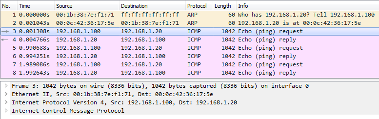
2.1.- En el segmento LAN:
C:\>ping 192.168.1.20 -l 1000
Haciendo ping a 192.168.1.20 con 1000 bytes de datos:
Respuesta desde 192.168.1.20: bytes=1000 tiempo=4ms TTL=64
Respuesta desde 192.168.1.20: bytes=1000 tiempo=4ms TTL=64
Respuesta desde 192.168.1.20: bytes=1000 tiempo=4ms TTL=64
Respuesta desde 192.168.1.20: bytes=1000 tiempo=4ms TTL=64
C:\>arp -a
Interfaz: 192.168.1.100 --- 0xb
Dirección de Internet Dirección física Tipo
192.168.1.20
00-0c-42-36-17-5e dinámico
C:\>
2.2.- En el segmento WAN:
2.2.1.- Solicitud de echo:
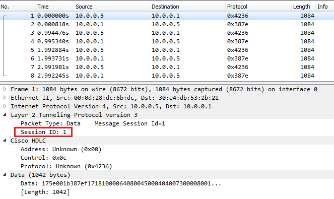
2.2.2.- Respuesta de
echo:
2.3.- En el router 1:
Cisco-1941#sh
xconnect all detail
Legend:
XC ST=Xconnect State S1=Segment1
State S2=Segment2 State
UP=Up DN=Down AD=Admin Down IA=Inactive
SB=Standby RV=Recovering NH=No Hardware
XC ST
Segment 1 S1
Segment 2 S2
------+---------------------------------+--+---------------------------------+--
UP
ac Gi0/0(Ethernet) UP l2tp 10.0.0.5:1 UP
Interworking: none Session ID: 1
(manual)
Tunnel ID: 0
Protocol State: UP
Remote Circuit State: UP
pw-class: L2TP
Cisco-1941#
2.3.- En el router 2:
Cisco-2801#sh
xconnect all detail
Legend: XC ST=Xconnect State, S1=Segment1
State, S2=Segment2 State
UP=Up, DN=Down, AD=Admin Down, IA=Inactive,
NH=No Hardware
XC ST
Segment 1 S1 Segment
2 S2
------+---------------------------------+--+---------------------------------+--
UP
ac Fa0/0(Ethernet) UP l2tp 10.0.0.1:1 UP
Interworking: none Session ID: 2 (manual)
Tunnel ID: 0
Protocol State: UP
Remote
Circuit State: UP
pw-class: L2TP
Cisco-2801#
3.- Pruebas de spanning-tree:
Aquí verificamos el envío de tramas STP (puramente de layer 2) por el tunel y por
el enlace P2P por radio, recordemos que al tener dos enlaces de layer 2 en paralelo
formamos un bucle que es protegido, justamente por STP.
3.1.- Verificación
inicial:
Catalyst-2950#sh spanning-tree vlan 100
VLAN0100
Spanning tree enabled protocol rstp
Root
ID Priority 32868
Address 0011.bb86.5280
This bridge is the root
Hello Time 2 sec Max Age 20 sec Forward Delay 15 sec
Bridge
ID Priority 32868
(priority 32768 sys-id-ext 100)
Address 0011.bb86.5280
Hello Time 2 sec Max Age 20 sec Forward Delay 15 sec
Aging Time 15
Interface
Role Sts Cost Prio.Nbr Type
---------------- ---- --- --------- --------
--------------------------------
Fa0/1
Desg FWD 19 128.1 Edge P2p
Fa0/2 Back BLK 19 128.2
P2p
(conexión L2TP)
Fa0/3 Desg FWD 19 16.3 P2p (conexión fibra/radio)
Catalyst-2950#
3.2.- Simulamos caida de enlace principal por fibra/radio:
00:47:08: %LINEPROTO-5-UPDOWN: Line protocol on
Interface FastEthernet0/3, changed state to down
00:47:09: %LINK-3-UPDOWN: Interface FastEthernet0/3,
changed state to down
3.3.- Verificación del
backup:
Catalyst-2950#sh spanning-tree vlan 100
VLAN0100
Spanning tree enabled protocol rstp
Root
ID Priority 32868
Address 0011.bb86.5280
This bridge is the root
Hello Time 2 sec Max Age 20 sec Forward Delay 15 sec
Bridge
ID Priority 32868
(priority 32768 sys-id-ext 100)
Address 0011.bb86.5280
Hello Time 2 sec Max Age 20 sec Forward Delay 15 sec
Aging Time 300
Interface
Role Sts Cost Prio.Nbr Type
---------------- ---- --- --------- --------
--------------------------------
Fa0/1
Desg FWD 19 128.1 Edge P2p
Fa0/2 Desg FWD 19 128.2
Edge P2p
(conexión L2TP)
Catalyst-2950#
En la vida real, al tener un enlace P2P por radio que no sea 100% estable, o el enlace WAN
mismo, pueden perderse tramas STP (BPDU) ocasionando inconsistencias de layer 2
bastante difíciles de solucionar (pensemos si se podría priorizar mediante QoS tráfico STP).
4.- Configuración de los equipos:
Cisco-2801#sh runn
Building configuration...
Current configuration : 936 bytes
!
version 12.4
!
hostname Cisco-2801
!
pseudowire-class L2TP
encapsulation
l2tpv3
protocol
none
ip local
interface FastEthernet0/1
!
!
interface FastEthernet0/0
description LAN
no ip
address
xconnect
10.0.0.1 1 encapsulation l2tpv3 manual pw-class L2TP
l2tp id
2 1
!
interface FastEthernet0/1
description WAN
ip
address 10.0.0.5 255.255.255.252
!
router ospf 1
log-adjacency-changes
network
10.0.0.4 0.0.0.3 area 0
!
line con 0
line aux 0
line vty 0 4
login
!
end
Cisco-2801#
WAN#sh
runn
Building configuration...
Current configuration : 1649 bytes
!
hostname WAN
!
interface FastEthernet0/0
ip
address 10.0.0.6 255.255.255.252
!
interface Ethernet1/0
description WAN
ip
address 10.0.0.2 255.255.255.252
ip ospf
cost 1
!
router ospf 1
log-adjacency-changes
network
10.0.0.0 0.0.0.3 area 0
network
10.0.0.4 0.0.0.3 area 0
!
line con 0
line aux 0
line vty 0 4
login
!
end
WAN#
Cisco-1941#sh
runn
Building configuration...
Current configuration : 2412 bytes
!
version 15.0
!
hostname Cisco-1941
!
pseudowire-class L2TP
encapsulation l2tpv3
protocol
none
ip local
interface GigabitEthernet0/1
!
!
interface GigabitEthernet0/0
no ip
address
ip
virtual-reassembly
xconnect
10.0.0.5 1 encapsulation l2tpv3 manual pw-class L2TP
l2tp id
1 2
!
!
interface GigabitEthernet0/1
ip
address 10.0.0.1 255.255.255.252
!
!
router ospf 1
log-adjacency-changes
network
10.0.0.0 0.0.0.3 area 0
!
line con 0
line aux 0
line vty 0 4
password
cisco
login
!
end
Cisco-1941#
(2018) Rebel
packets open tunnels to freedom
Rosario, Argentina